Building a desktop train departure sign
January 20, 2026 | 13 min read
Last September during my trip to the UK we became stranded at a small town train station because a tree had fallen on the tracks nearby. After waiting at the station in the rain for much too long, we decided to have a drink at a pub across the street until the service was restored.
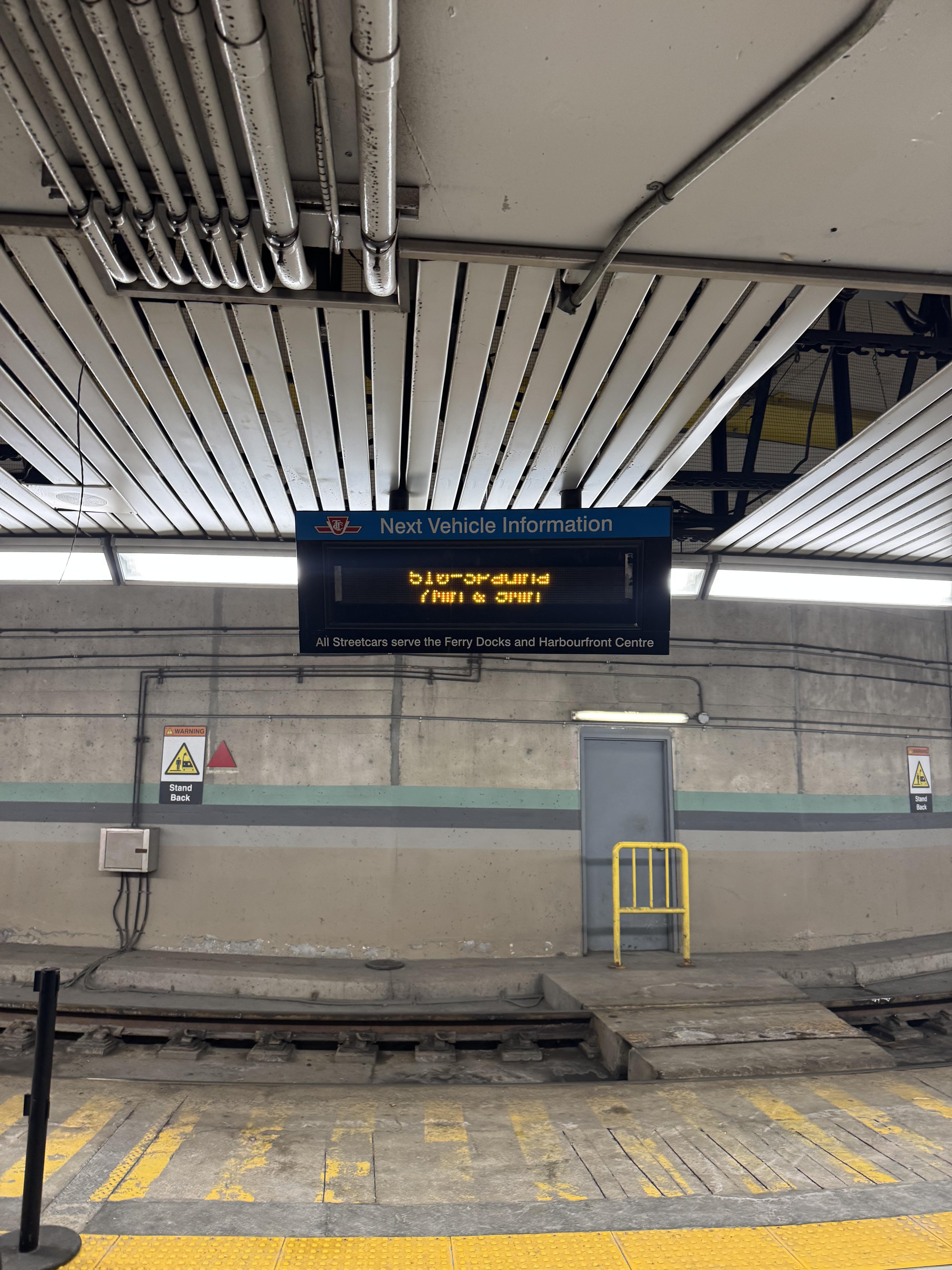
At the pub I saw this sign:
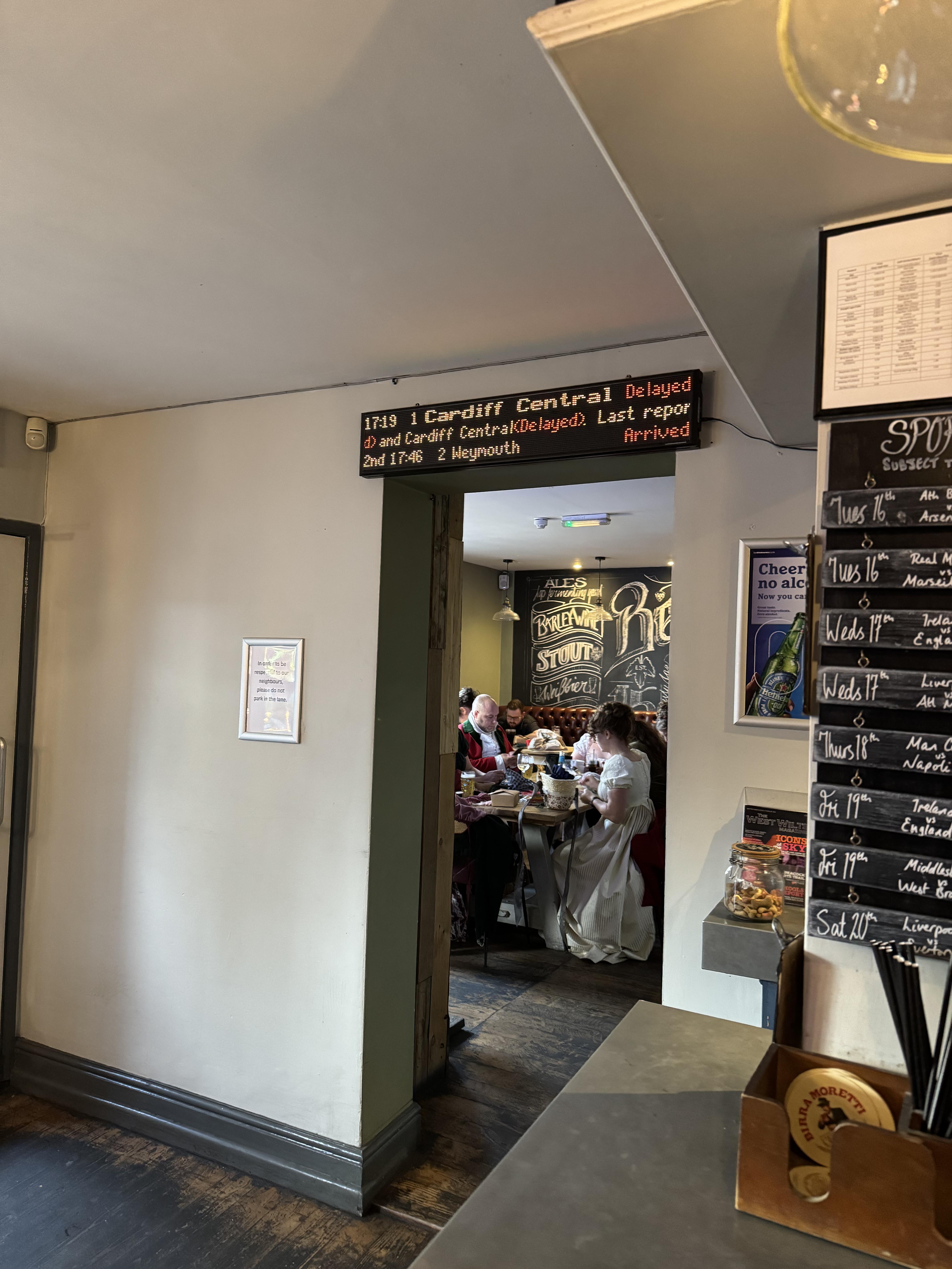
The sign looked similar to the ones on the platform, but I talked to the owner about it and he said it wasn’t an official sign. He told me that he ordered it online.
I thought to myself, it’d be nice to have something like this in my condo so I know when to leave to catch the streetcar.1
Existing train departure signs
Consumed by the idea of having a sign like this in my home, I did some research to see if this kind of thing had been done before. It has (link, link), but unfortunately these projects weren’t quite to my liking despite being pretty cool themselves.
I had some specific requirements:
The screen should be bigger than 2 inches. The existing projects are all tiny, and I felt that I wanted a sign that look like it could (maybe) be an official TTC sign.
The screen should have individual LEDs. TFT LCD displays are nice, but that’s not the type of look I’m going for here.
The LEDs should be RGB. This is purely a personal preference, but I felt like the multiple colours of the UK departure board looked really cool and I wanted to have the flexibility of showing a wide range of content later anyway.
The resolution should be at least 256x64. I wanted the ability to display multiple lines of content at multiple font weights, etc.
Unfortunately, it was very difficult to find a 256x64 display that was bigger than 2 inches wide and smaller than half a metre, so the train sign idea was shelved.
We have train sign at home
At Christmas time I became motivated enough again to do something with this idea.
I remembered that I had three old 32x16 HUB75 panels laying around, left over from an old company Hackathon project where I used them for a stock ticker. I also had a few ESP32s which I was reasonably sure could drive them.
After getting my partner’s opinions, I was told that making this sign 3 panels across would be too big, so this sign would have to be 2 panels wide instead.
Powering the panel
I excitedly wired the panels together using DuPont cables because I’d lost the official Adafruit ribbon cables.
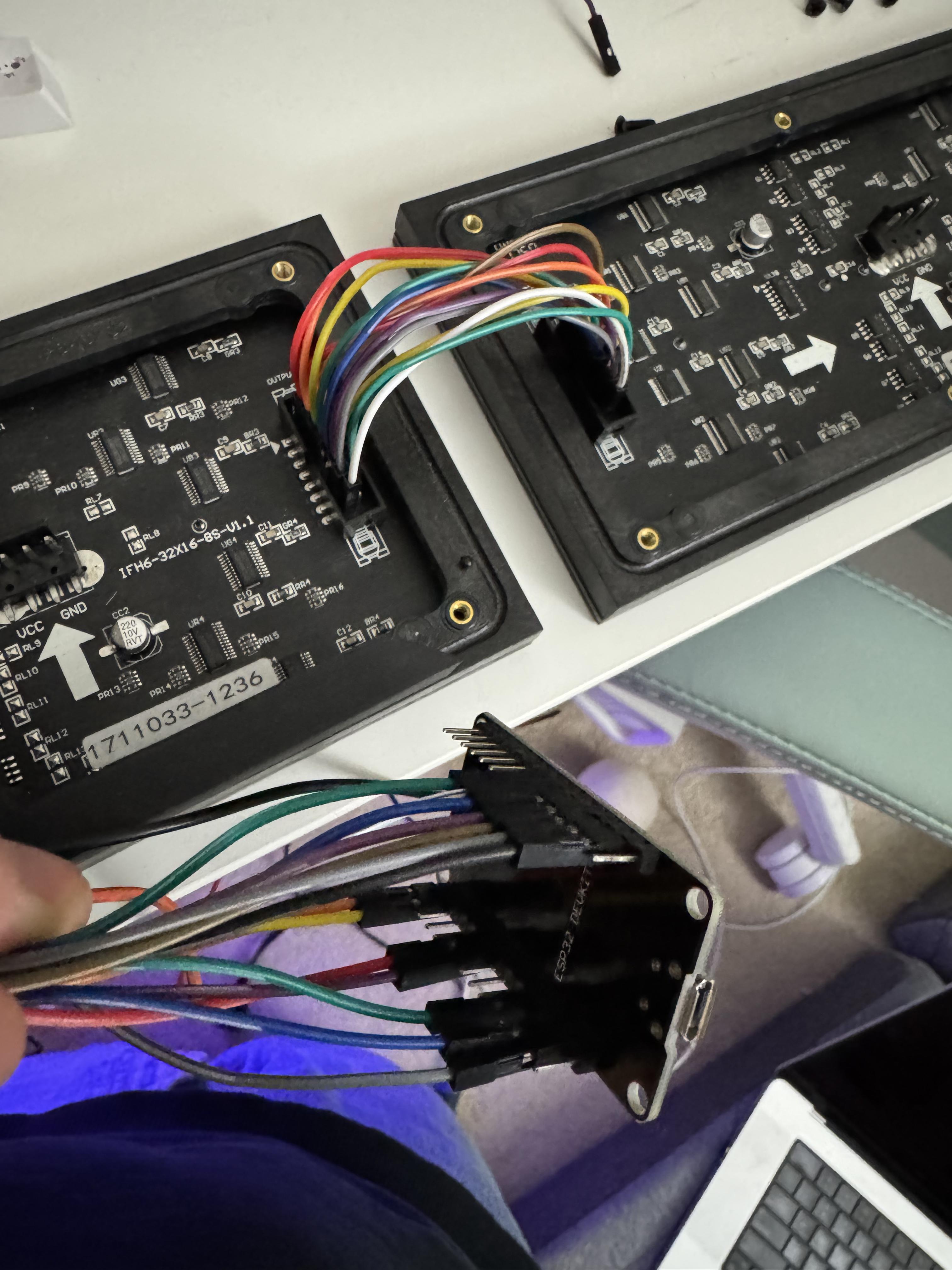
I am not an electrical engineer by any means, so I was relying a combination of ChatGPT and critical thinking for this project. ChatGPT heavily advised me not to power the panels with the USB cable from my computer: the logic being that each panel can draw up to 4A of current at full brightness, so I needed an 8A power supply.
All the 5V 8A power cables looked excessive, so I pinky promised that I’d never have both panels fully white at maximum brightness and ordered a 4A power supply instead, as well as some barrel connectors.
I figured that during prototyping I could use one of those fancy variable power supplies that I see electronics people using all the time, so I ordered one of those on Amazon.
Since I didn’t have any means of getting 5V 4A that day (believe me, I checked every USB wall wart in the house) I waited for my power supply and power cable to arrive in the mail.
Designing the case
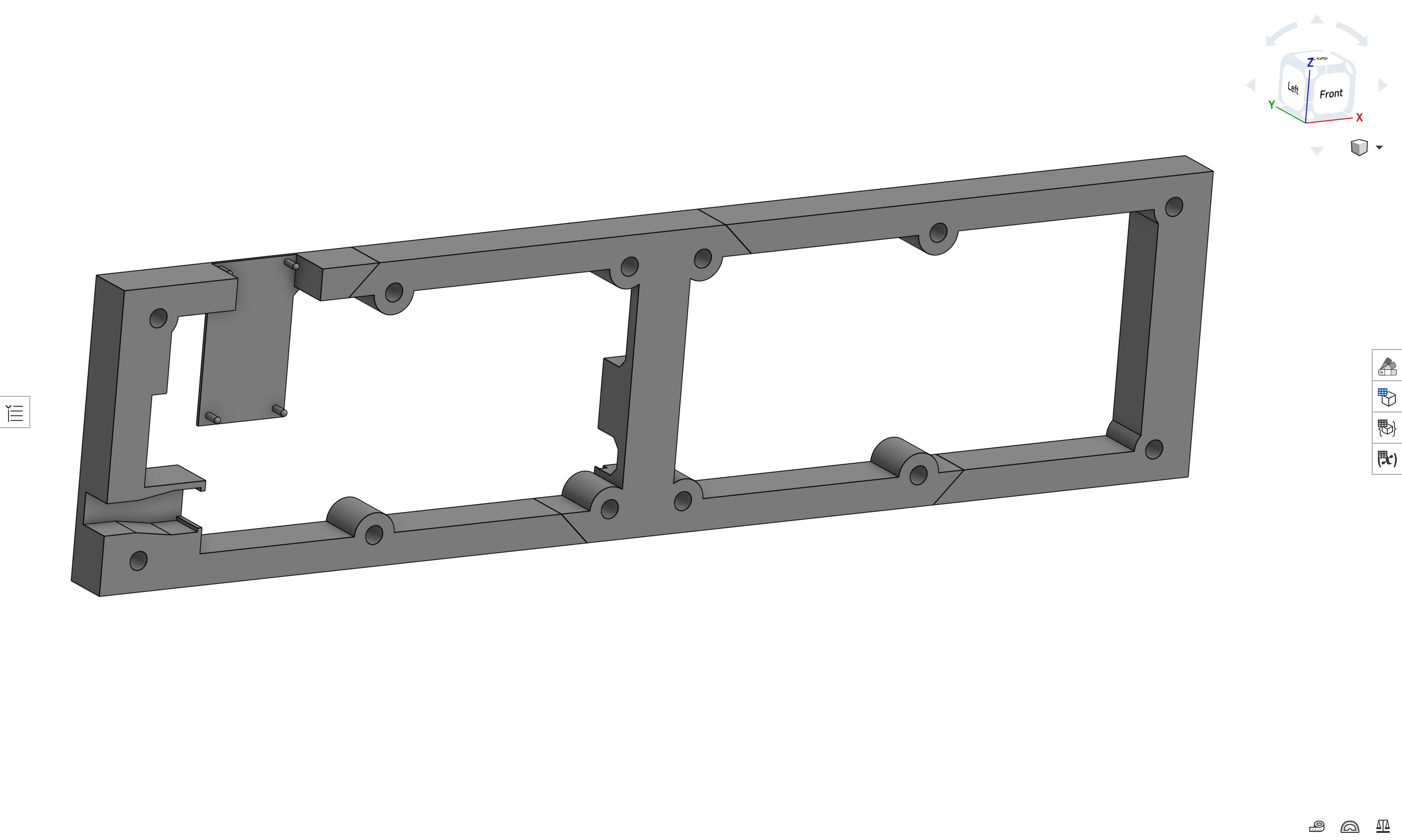
I figured I might as well start designing the 3D printed case while I waited. It’s not really a “case” and more of an open “backer” to contain the mess of wires behind the panels and provide a way to mount it to the wall.
My idea was that I’d hang it using command strips (I rent) so I would design vertical flat space in the back for those to stick to.
Since the LED panels already have threaded screw inserts in them, I could just attach the case to the panels by screwing them in directly.
One design challenge was figuring out how the ESP32 would be fixed to the case. Since the chip doesn’t have attachment points, I ended up making poles for it to sit on, which looked really silly.
Thankfully, the final version of the case ended up looking much cleaner.
Programming the ESP32
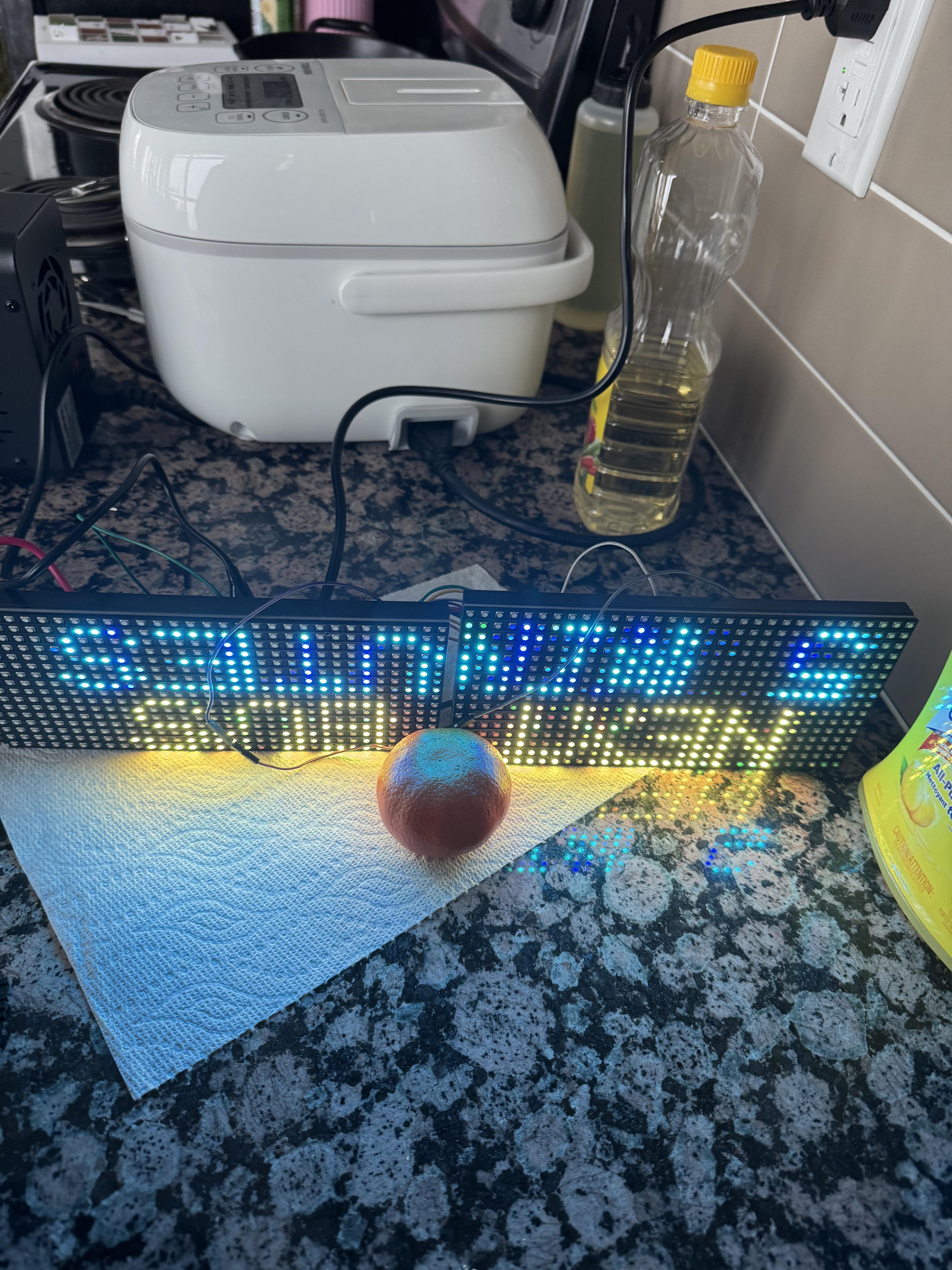
Once my shiny new power cable and variable power supply arrived, I powered up the panels using the alligator cables so I could begin testing the nearly decade-old panels to see if they still even worked.
Displaying text
I started by trying to display a few lines of text on the panels.
Before AI, I would’ve started by finding some example code that displays text and then adapting it to meet my needs.
But now that we have AI at our disposal, it seemed like a good idea to ask it for an Arduino project that was already adapted to my needs.
This did not end up saving me any time.
AI did output a program that looked correct, and it correctly recommended to use the ESP32-HUB75-MatrixPanel-DMA library, which is arguably the library to use for the ESP32 + HUB75, but nothing that it outputted compiled because it kept hallucinating incorrect header filenames.
In an attempt to compromise with the AI, I asked what version of the library it was familiar with and installed that version instead, but it still didn’t get the header filenames correct. After I gave it the correct header filename, it started hallucinating non-existing APIs.
I ended up just using an example project from the library’s repo and basing my output off of that, and if I had done that from the start I would’ve saved a lot of time up front.
Productionizing
Text now displayed properly on the screen, but there was a blurriness and some flickering.
I reasoned that this must be because the DuPont cables are too small and not shielded properly.
I wanted to start soldering wires together so I could get away from the DuPont cable disaster, but I became a bit overwhelmed and couldn’t see an easy way to make my mess of cables production-ready.
After some research I decided to order some ribbon cables from Amazon to clean up the connection between the two panels, as well as the correct power cable for the panels from Adafruit.
I also discovered the ESP32-Trinity, an ESP32 that’s designed specifically for use with HUB75 matrix panels and plugs directly into the panels, so I ordered that as well.
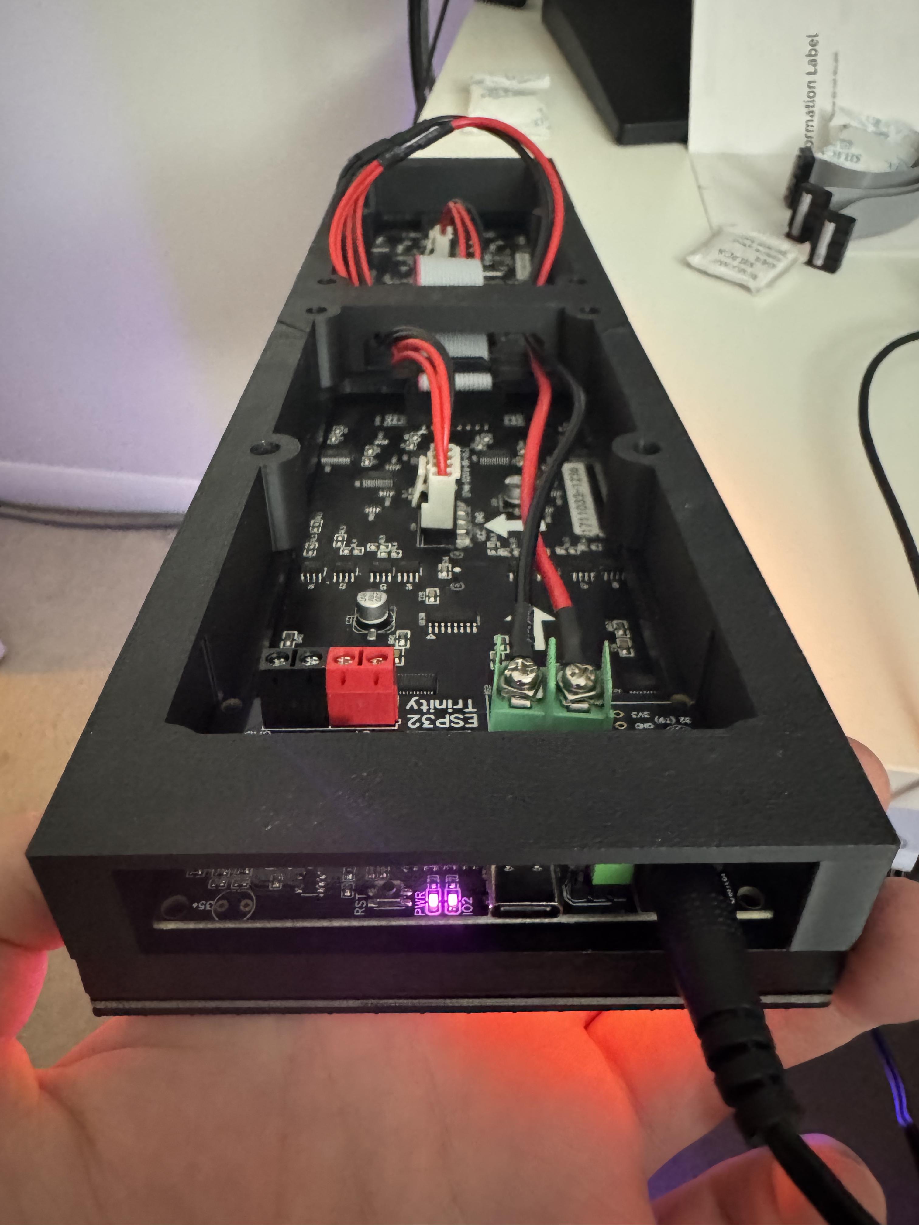
Once I received the Trinity board I took some measurements and greatly simplified my case design.
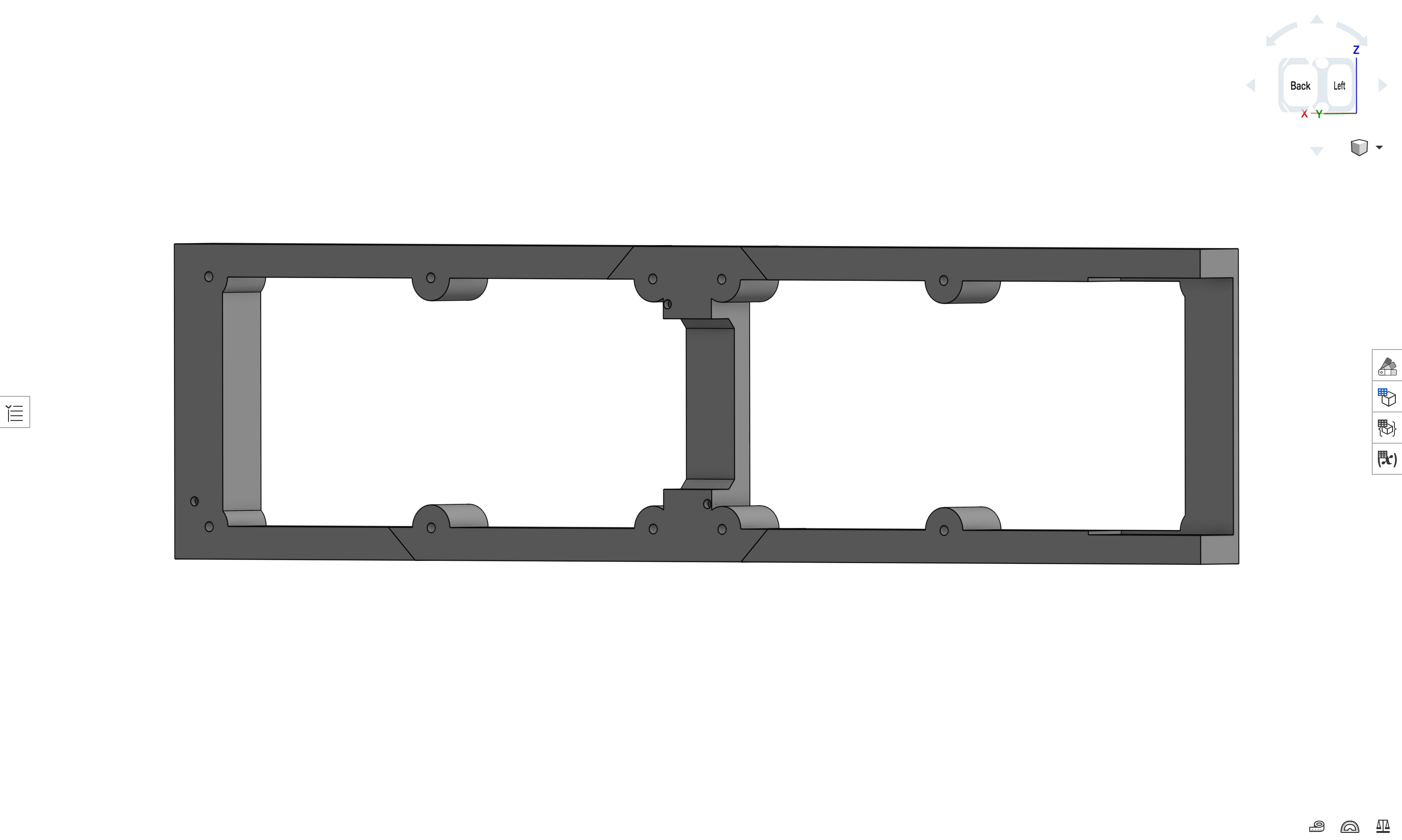
Here’s what it looked like after print and assembly:
Sourcing streetcar times
To fetch streetcar times I planned on using whatever API tobus.ca was using, because I find their times to be accurate and I like their to-the-second estimates.
AI was really helpful for writing the logic to fetch updated times every 30 seconds and parsing the JSON that came back to display.
Sorting the times and formatting the text was simple, and I ended up going with this format:
###  MMm:SSs
###  MMm:SSs
where ### is the streetcar line number and MMm:SSs is the to-the-second time until the next streetcar.
It displays the next 2 streetcars regardless of line number at my local stop, but filters out any streetcars that are less than 3 minutes away, because there’s no way I can get outside to the stop in less than 3 minutes.
Debugging the hardware
The sign was finally complete!
Unfortunately, when powering it on the text was blurry and flickered despite having the proper cables and stable connections.
I managed to find this Github issue going over common problems and their fixes, and disabling the clock phase (clkphase = false) did seem to improve the quality for me, but there was still a faint flicker.
I noticed the flicker sometimes disappeared when I jiggled the power cable a certain way, so I concluded that must be something wrong with the power supply.
I checked with a multimeter and saw that I was getting 5.41V from the jack, so it certainly wasn’t undervoltage that was causing the flicker, but possibly overvoltage instead. To confirm, I set up my desktop power supply and observed that 5.0V looked perfect with no flicker, but unfortunately 5.4V looked perfect too.
After beginning to doubt the consistency of the power from the barrel jack I almost ordered a small oscilloscope, but then I talked myself out of it.
I noticed that my sign was never drawing even more than 500mA of current from the power supply, so it occurred to me that I could safely use USB to power the sign.
Thankfully the Trinity board supports being powered by USB-C by simply moving a jumper pin, so I switched it and everything is now flicker-free.
Improvements I probably won’t make
I’m fairly happy with the state of the project as it is, but there are some potential improvements:
Make it look more like a TTC sign. The actual TTC sign at Union Station, despite having the same height as mine, shows the next 4 streetcars by alternating between streetcar lines every ~10 seconds and showing the next 2 cars for each.
A front cover. Either in the form of a clear perspex sheet, or if I end up using it for other purposes, some kind of 3D printed diffuser.
Automatic orientation using an accelerometer. If I wanted the USB port to be on the opposite end of the sign I’d have to rotate it, but then I’d have to flip the text that’s being displayed in the ESP32 so it’s readable. However, the ESP32-Trinity project supports an accelerometer, which I could use to determine the orientation of the sign so I could just flip it and have the screen automatically rotate like a phone.
Physical buttons. It’d be neat to have buttons to switch “apps” on the sign, e.g. if I wanted to switch between a stock ticker, news, and streetcar times. Bonus points if they were radio-button-esque.
Configuration via web interface. Since the ESP32 is WiFi-connected anyway, it could host a web server where I could switch “apps” remotely, submit custom text to display on it for events, etc. You could even accept custom apps via the web interface in a higher level language like Lua.
Conclusion
My original plan was to have the sign in the entrance of my condo, but for now the sign just sits on my desk. It actually has helped me leave the house just in time to catch the streetcar.
If anyone would like to make a display like this themselves, here’s the parts list, and it requires no soldering:
And in case the panels don’t already come with them (I don’t remember):
- 20mm x 10mm IDC Ribbon Cable (I just got mine on Amazon)
- RGB LED Matrix power cable
You can find the printable model for the case in OnShape here, and the source code will be published soon.
-
I realize I could’ve just use an app on my phone to see when the streetcar is coming, but that’s not as cool. ↩